FreeRTOS setup on the Nucleo
| authors: | Furkan Ali Yurdakul |
|---|---|
| date: | May 2020 |
Description
Embedded bare-metal hardware needs some adjustments to make proper use of DDS. These kinds of hardware are mainly not suited for software operating in Real-Time. DDS will work when the communication operates in a non-Real-Time software, but will lose its purpose. Because of this, the software would need an OS to make the Nucleo operate in Real-time. In this guide, FreeRTOS will be used to run two tasks simultaneously, which are for toggling LEDs at a different speed.
- For this tutorial the following products have been used:
- Nucleo
- Lenovo Thinkpad T470 (Windows)
- Micro USB cable
- STM32CubeIDE
Real-Time OS
There are multiple Operating Systems that are Real-Time OS (RTOS) with a focus on microcontrollers from 8- to 32-bits. Some examples of RTOSes are VxWorks, QNX, Win CE, pSOS, Nucleus® RTOS, NuttX, and FreeRTOS™. RTOSes enable to run multiple tasks and schedule them according to a preemptive scheduling algorithm at the same time with usages of interrupts. More about RTOSes.
These RTOSes all have the same purpose, but the way how the RTOS is making use of the memory and/or interrupts will have an impact on the latency of the RTOS. This guide is not to show how we could improve the speed of the communication using DDS, but rather how to use the protocol itself. In this case it doesn’t matter which RTOS is chosen, as long as it’s compatible with the Nucleo.
The decision for the best RTOS has been made by taking into consideration if there is enough support/documentation to be found on- or offline, and the accessibility of the RTOS. The datasheet of the Nucleo shows the support and usage of FreeRTOS.
The webpage of FreeRTOS mentions the software being open-source and makes use of an MIT-License. The reasons elaborated above make the usage of FreeRTOS optimal for this project and there is no need to look any further.
Implementation of FreeRTOS
Let’s start with making a clean project for this guide. If you have trouble or forgot how to do this, see “How to setup the Nucleo” how to make a clean project specifically for the Nucleo. You can name this project anything you want since it will not be used for the end product, but only to test FreeRTOS. For this guide the project is called “FreeRTOS”.
2 on-board LEDs will be used to test how to make 2 tasks run simultaneously. For this we need to enable 2 pins as output. Open the “.ioc” file and look for “GPIO” under the section “System Core”. If a clean build was made, this is how it should look like.
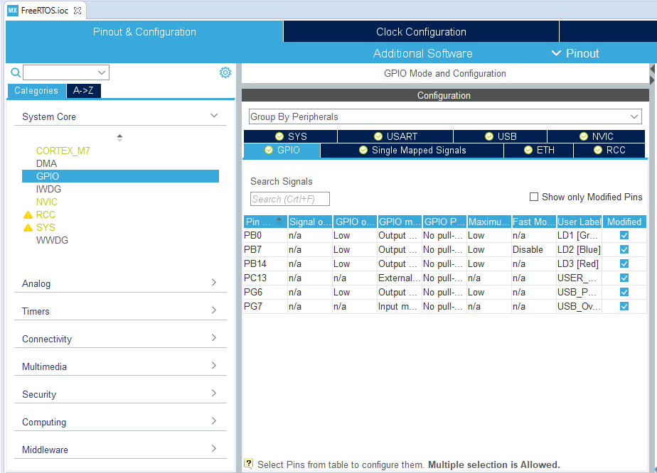
The on-board LEDs are preselected and the labels should be visible as LD1 [Green], LD2 [Blue] and LD3 [Red].
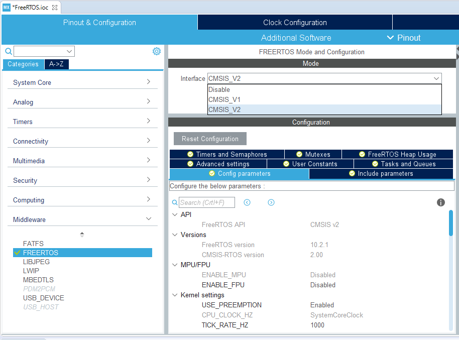
In the “Middleware” section you can find the FreeRTOS interface. Set the interface to CMSIS_V2(CMSIS_V1 is just an older API version) to enable the use of FreeRTOS.
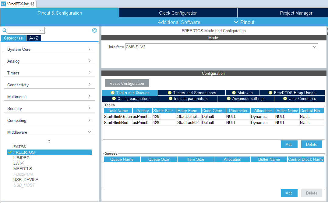
This guide will show how to toggle 2 different LEDs at different speeds. For this, we will need 2 tasks which can be created in the tab called “Tasks and Queues”. The tasks made for this guide are called StartBlinkGreen and StartBlinkRed, and entry function names are BlinkGreen and BlinkRed. Judged by the name, BlinkGreen will toggle the green LED on and off and the BlinkRed will do the same for the red LED.
When everything is done as above and matches the pictures, continue with the next part. This part explains and implements the change for the timebase source.
System Timer
The HAL, an STM32 embedded software layer that ensures maximized portability across the STM32 portfolio, makes use of a unique timebase source. The RTOS has full control over this source and most RTOSes force the system timer(SysTick) priority to be the lowest. For this reason, the timebase source will be changed from SysTick to a less commonly used timer. In the note below, you can find a quote taken from the datasheet of the STM32CubeIDE, which explains why exactly it is better to use a different timebase source instead of the SysTick (datasheet).
Note
“By default, the STM32Cube HAL is built around a unique timebase source, the Arm® Cortex® system timer (SysTick).
However, HAL-timebase related functions are defined as weak so that they can be overloaded to use another hardware timebase source. This is strongly recommended when the application uses an RTOS, since this middleware has full control on the SysTick configuration (tick and priority) and most RTOSs force the SysTick priority to be the lowest.
Using the SysTick remains acceptable if the application respects the HAL programming model, that is, does not perform any call to HAL timebase services within an Interrupt Service Request context (no dead lock issue).”
This project doesn’t make use of any timers yet but taken into consideration for the future purpose of this project a basic timer will be used. Based on the datasheet of the Nucleo, timer 6(TIM6) and timer 7(TIM7) are the basic 16-bit timers. To prevent conflicts in the future the timebase source will be TIM6.
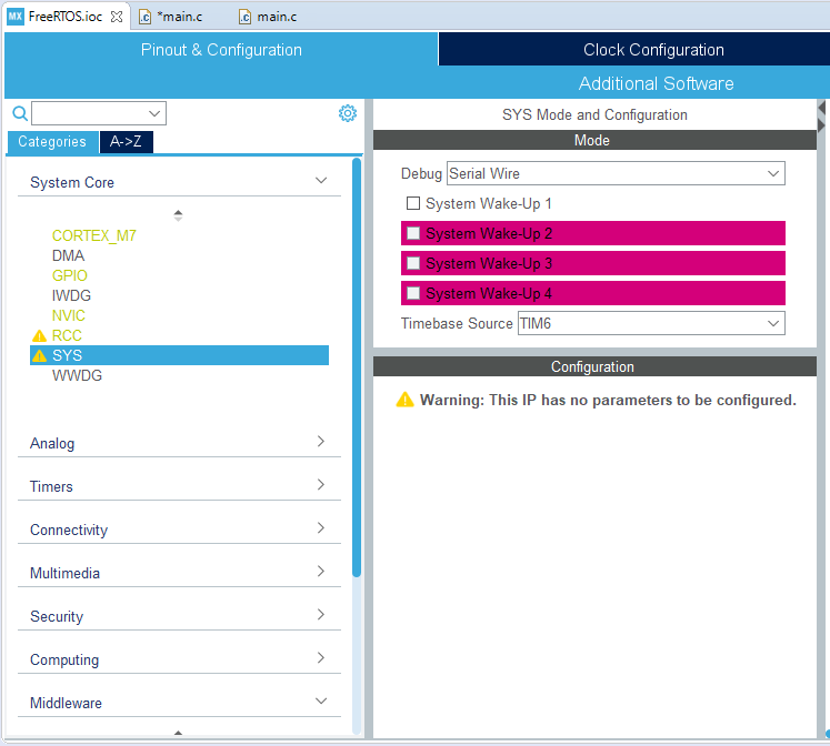
To do this open the category “System Core” and open “SYS”. Here we can change the timebase source to TIM6.
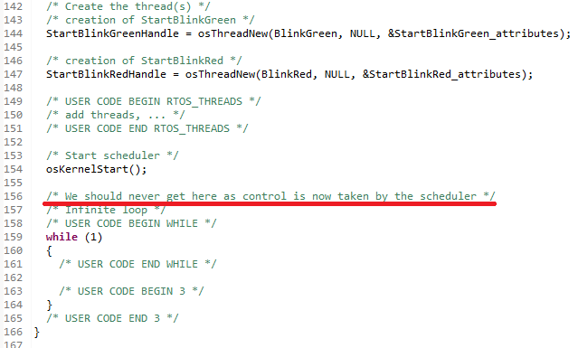
After everything is selected, close the “.ioc” file and accept to generate the code. This would create all the software needed for FreeRTOS and the tasks for it.
Testing FreeRTOS
From now on all the coding will be done within the created tasks and not in the main while loop. This is because the system is taken over by the FreeRTOS.
To toggle the LEDs, the software will make use of HAL_GPIO_TogglePin() command. To show that the system can run multiple tasks at the same time we will use a delay to toggle the LEDs. The command osDelay() will be used to create a delay. Without an RTOS the delays should conflict the frequency of the LEDs toggling on and off. For this test the green LED will toggle every second and the red LED will toggle every half second. The image below shows the implementation for toggling the pins and the used delays.
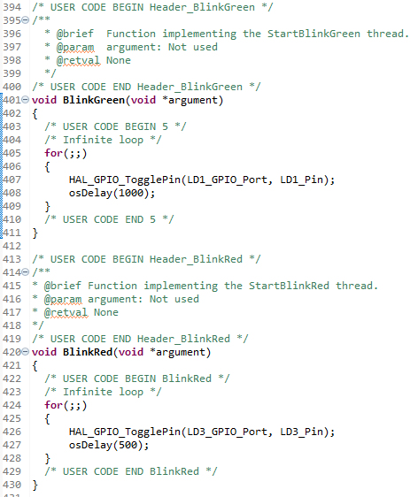
After everything is done, save and compile the “main.c” file. the compilation shouldn’t give any conflicts. If it does delete the written code a rewrite matching the image above. If it doesn’t give any conflicts, flash the software on the Nucleo. The Nucleo should toggle the green LED every second and the red LED twice as fast. This shows that the 2 tasks, which both have delays build in, can run at the same time.
This allows us to have a Real-Time system and are ready to continue with the next step. The next step, “Libraries for DDS on bare-metal”, explains what kind of libraries are needed and how they are implemented to make use of the communication protocol DDS.