Serial Communication with the Nucleo
| authors: | Furkan Ali Yurdakul |
|---|---|
| date: | April 2020 |
In this page, there will be a step by step tutorial to make sure your Nucleo can make use of USART to send data to your computer with the use of a micro USB cable. The expected result is to receive the same message back that will be sent from a computer.
- For this tutorial the following products have been used:
- Nucleo
- Lenovo Thinkpad T470 (Windows)
- Micro USB cable
- STM32CubeIDE
- Hercules (Terminal)
Hardware Pinout
The Nucleo can have multiple USART communications, these can be found in the datasheet. The one that will be used for serial communication between a computer and a Nucleo is USART3.
The reason behind this is because the datasheet specifically tells that USART3 uses the output for ST-Link, also known as the port where the micro USB is connected.
USART3 can also be reconfigured to make use of the ST morpho output. This can be done if a specific solder bridge is changed, see the image below. But since this is not preferred, the default configuration for the solder bridges will be used. If your board doesn’t have the default configuration, see the image below which settings are needed to use ST-Link as the output for USART3.
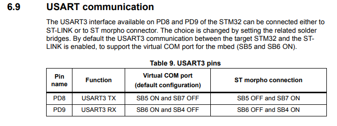
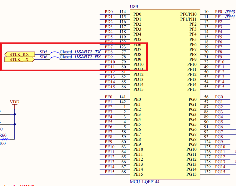
See the following image for the hardware pinout how the pins are connected to ST-link.
The next step is to initialize the USART3 in the Nucleo.
Initialize USART3
To initialize USART3 for the Nucleo, you simply need to open the “.ioc” file in the STM32CubeIDE. The USART3 can be found in the Connectivity section, click on it. Set mode to Asynchronous and change the Baud Rate to 9600 Bits/s. Asynchronous is used, because there is no clock signal used for the communication. The Baud Rate is lowered to ensure stability over speed, because speed is not a necessity in for this tutorial.
See the image below for how it should look like:
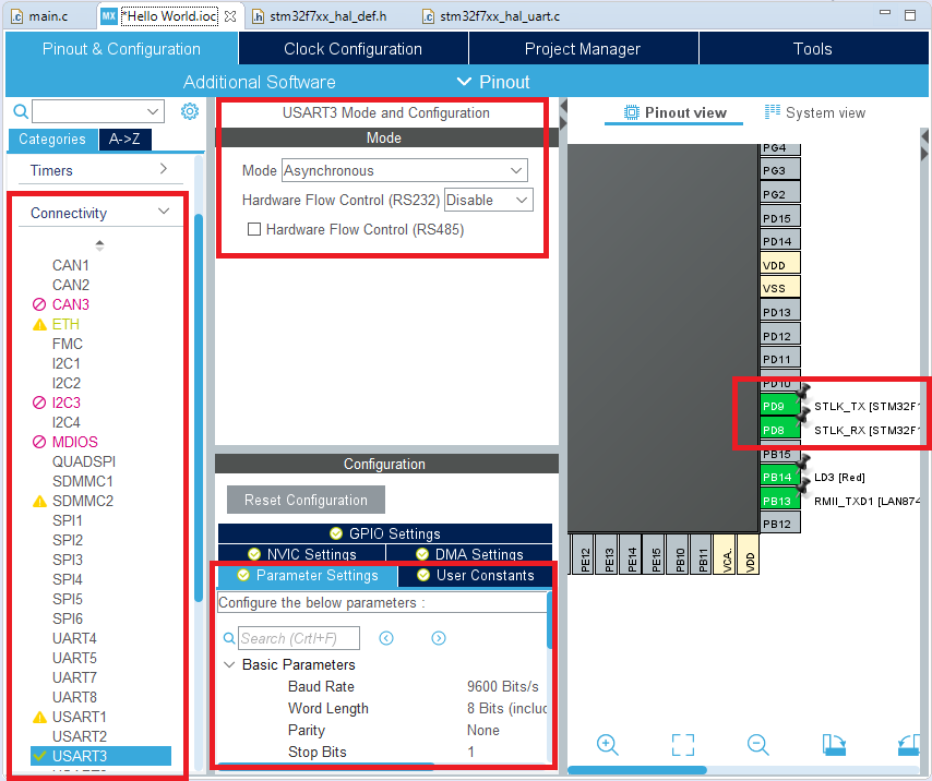
The pins PD8 and PD9 should be linked to ST-Link. To make sure the pins are linked, check the pinout view on the right side of the image.
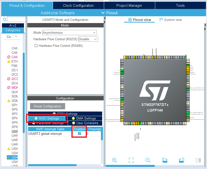
It is also a must to enable global interrupts for USART3. This can be done by going into the NVIC settings of the USART3. See the image below:
When your IDE User Interface is looking the same as the images, press CTRL+S to save it and click yes to generate code for the initialization. The next step will be to write the code and flash it on the Nucleo.
Code flashing
Because interrupts are used, we do not have to change the main code. The interrupts must ensure that the code for controlling the LED is not disturbed.
First, the received and transmitted characters must be stored so that they can be used to send it back. For this, 2 variables are created called rx_buff for the received message and tx_buff for the message to be sent.
These are added in the USER CODE 0 section:
/* USER CODE BEGIN 0 */
uint8_t tx_buff;
uint8_t rx_buff;
/* USER CODE END 0 */
The Nucleo will act as a slave since its only job is to echo the received messages. The receive interrupt must, therefore, be initialized first. This is done in the USER CODE 2 section:
/* USER CODE BEGIN 2 */
HAL_UART_Receive_IT(&huart3, &rx_buff, 1);
/* USER CODE END 2 */
A receive interrupt has been set for USART3. rx_buff is the variable where the received byte is stored and 1 represents the interrupt calls for each byte received. These are added in the USER CODE 4 section:
/* USER CODE BEGIN 4 */
void HAL_UART_RxCpltCallback(UART_HandleTypeDef *huart)
{
   tx_buff = rx_buff;

   HAL_UART_Transmit_IT(&huart3, &tx_buff, 1);
}
void HAL_UART_TxCpltCallback(UART_HandleTypeDef *huart)
{
   HAL_UART_Receive_IT(&huart3, &rx_buff, 1);
}
/* USER CODE END 4 */
A transmit interrupt for USART 3 has been set within the receive callback. This way the moment it’s done receiving the byte it will start transmitting it back.
When every piece of code is added, click on Run code and wait till it’s finished. This should flash the Nucleo without errors and you can continue with the next step. If not, delete all written code and redo this step. The code will be tested in the next step, with the use of a terminal.
Terminal
To communicate with the Nucleo, your computer needs software to receive and send serial data through your USB port(COM port). There are multiple good terminals someone could use as this is a matter of personal preference. There will be some recommended terminals down below:
In this tutorial Hercules is used, but there is no problem with using anything else that is capable of making a serial connection via any COM port. For Hercules, it should look like the image below:
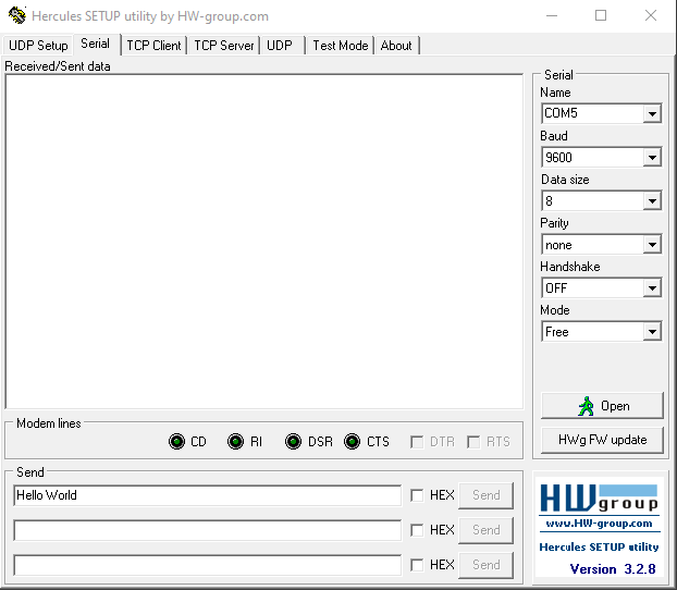
The settings for the terminal should be the same as the USART3 initialization of the Nucleo. Besides the settings, select the correct COM port in this case it was COM5.
End Result
After the terminal is set and the code is flashed on the Nucleo, send a message via the terminal and the Nucleo should send the same message back.
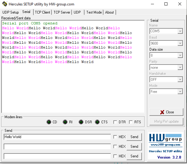
If it did work, this means your board is ready to make use of serial communication. Otherwise restart the process from Initialize USART3.